Something New - Something Powerful
Copyright George M. Bonnett, JD 2015 All Rights
Reserved
Introduction:
In order to put this in perspective, it is necessary to
start from where we have been. When
solving collisions back in the dark ages, the procedure for using Conservation
of Linear Momentum was the quadrant method.
Being new to accident reconstruction back in the late 70's, and having a
brand new HP-15C calculator and not knowing any better, I managed to program it
to solve Linear Momentum problems using just the two primary formulae for V2
and V1 using the trigonometry functions instead of using the very awkward
quadrant method. In fact, it could
handle four exit fragments for each of the two vehicles in collision.
In early 1986 several years after the formulae had been
given to IAARS, it was on a Radio Shack
PC-2 computer with a small 4 color ink-pen printer and was brought to an AI/AR
training institution to demonstrate to them a new way of doing Momentum
problems. They labeled it
"witchcraft" and unceremoniously told us to leave. For well over 5 years several other
institutions still taught the Quadrant method, even though the initial
institution had finally become a believer.
This method still required knowing all four angles and the departure
speeds immediately out of collision for both vehicles.
Back around 2009-10, while talking with a friend at the PSP
conference in Happy Valley, PA about solving for momentum with less information
using just one vehicle, concern was expressed that the departure angles for
both vehicles were needed to make this work. But what if we only had the CDR
data from one vehicle? There was an
experimental version of REC-TEC, but it required input of both the approach and
departure angles for the two vehicles, in addition to the weight of the second
vehicle. After release a few years ago,
another discussion revealed that my friend was now teaching almost exactly the
same method.
With this methodology integrated into Crush5, in 2015 it
was no longer necessary to input the approach angles as the migration from CDR
data to Crush5 enabled solving for them.
All that is left is solving for the 2 departure angles.
New for 2016 is the integration of Restitution (e) into the
Crush5 solution and the Vectors (EDM-Momentum) module. Knowing the approach angles gives us a Cone
of Departure for the collision. The
REC-TEC Vector module permits 2-variable table integration with Restitution
(e). It is possible that this, coupled
with the implications involving Plane of Impact has brought us ever closer to
finding a viable new solution.
Figure
612-IM42 (2016 Release)
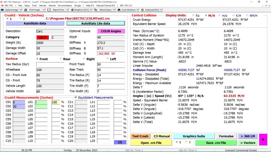
The only noticeable change on this screen is the Angles
| (e) | Speed (Vc) label on the right side of the screen. This has some exciting implications that
will be explored in following screens.
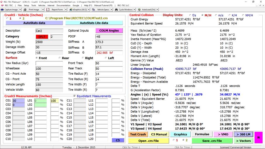
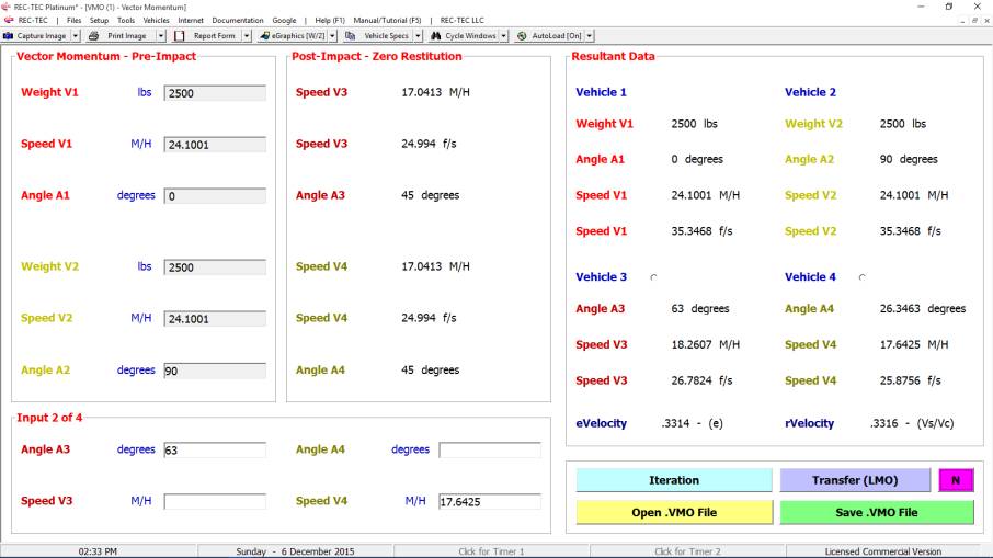
Figure
612-IM43
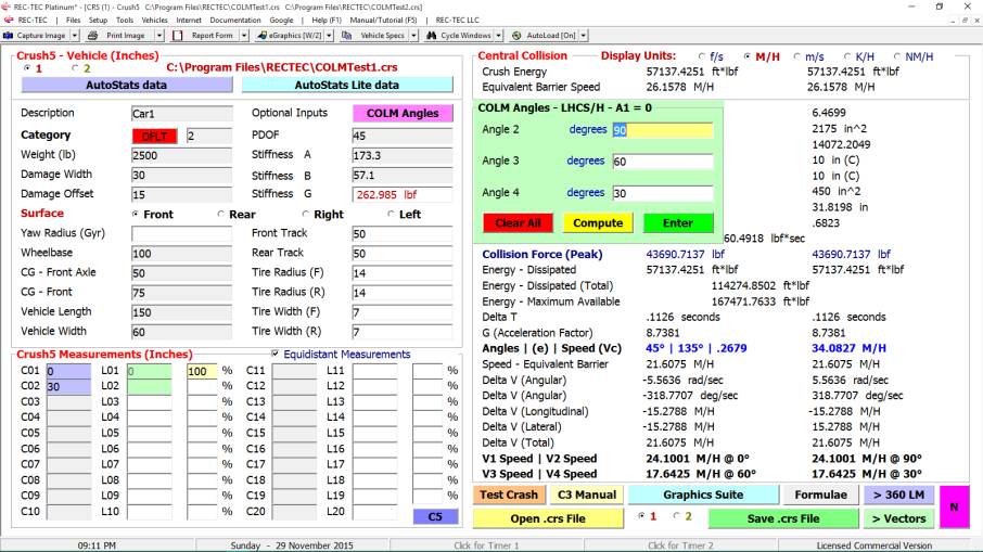
Clicking on the COLM button displays the COLM
Angles frame that will self-populate based on the PDOF angles (user
override available) of the
vehicles. Angles allow the program to
compute Speeds V1, V2, V3, and V4. REC-TEC can now compute Restitution
(e) based on the angles and speeds.
The reconstructionist is able to use his expertise to form truly
informed opinions from very limited data.
Figure
612-IM44
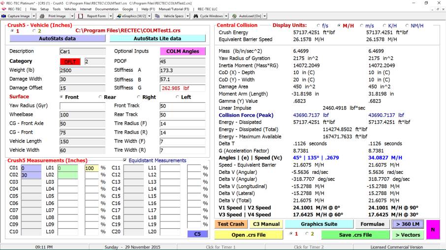
Figure 612-IM44 displays information on Vehicle 1.
Figure
612-IM45
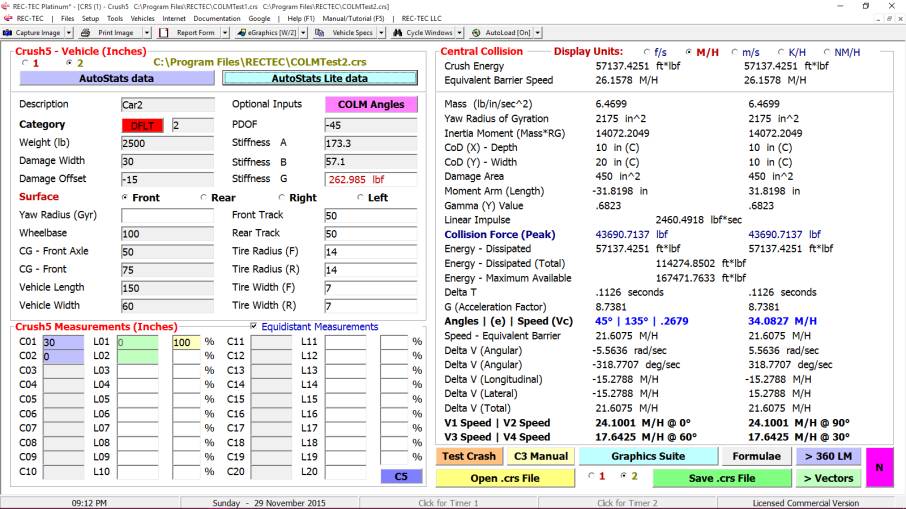
Figure 612-IM45 displays information on Vehicle 2.
Figure
612-IM46
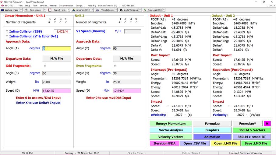
Figure 612-IM46 displays the information on Vehicle 1 and
Vehicle 2 transferred into 360 LM.
The eVelocity (Restitution) is recalculated in 360 LM
based on the data transferred from Crush5.
Figure
612-IM47
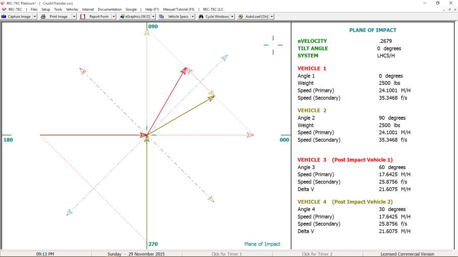
Figure 612-IM47 displays the Plane of Impact basis
for (e).
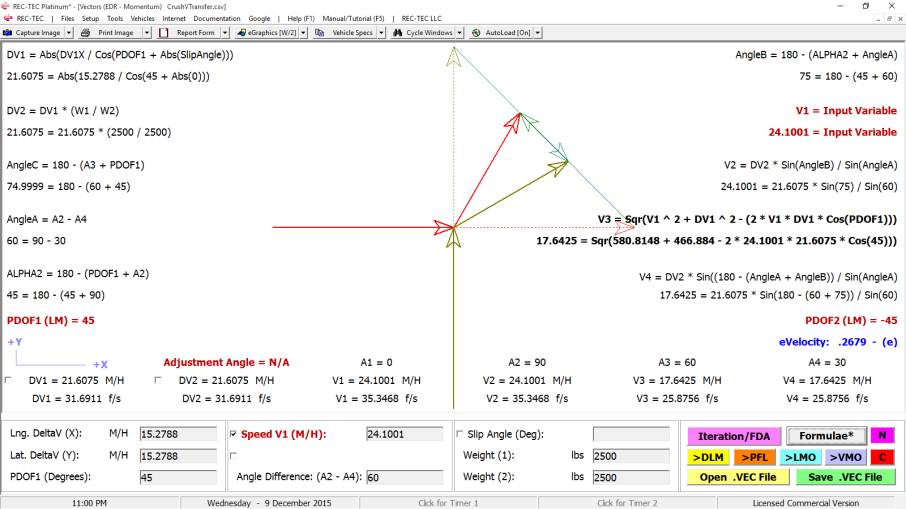
Figure
612-IM48
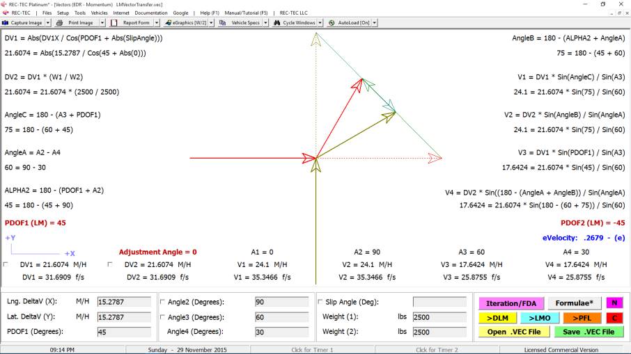
Figure 612-IM48 displays the information from 360 LM
transferred into Vectors (EDR - Momentum), along with a vector diagram
and the formulae used to arrive at the results in this module.
Figure
612-IM49
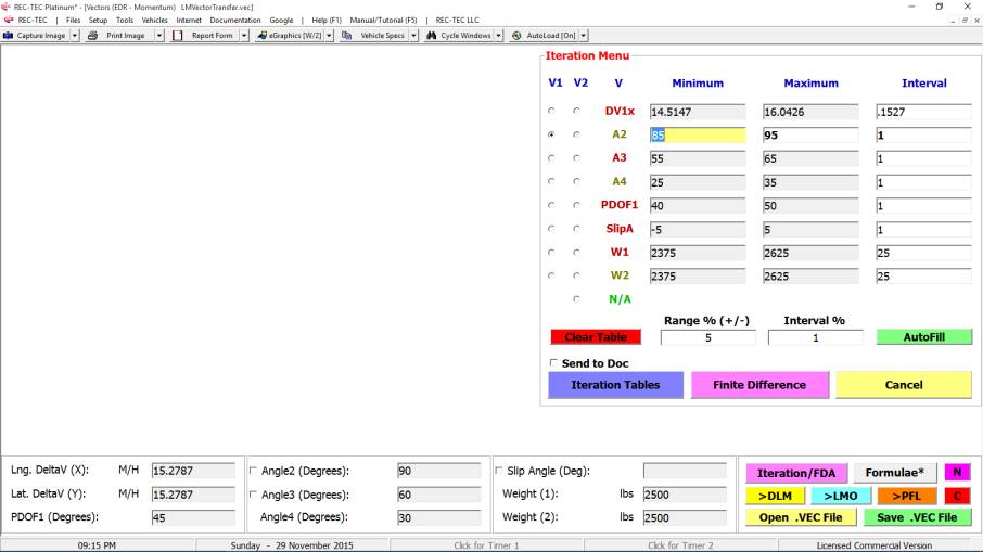
Figure 612-IM49 displays the Iteration / FDA (Finite
Difference Analysis) interface.
Employing the user set Range and Interval, Autofill
has populated the interface with Minimum, Maximum and Interval
information on the associated variables.
These can be overridden by the user.
Note that Iteration in this module can use two variables. Only Angle 2 has been selected here.
Figure
612-IM50
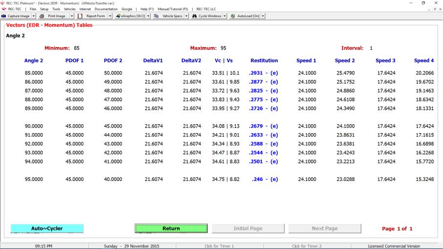
Figure
612-IM50 displays the Iteration screen for Angle 2 based on the
information on the Iteration / FDA interface.
Figure
612-IM51
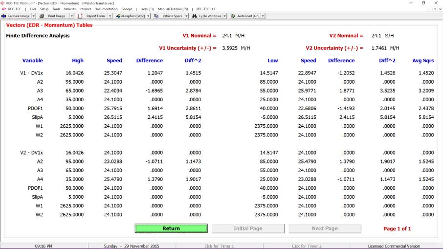
Figure
612-IM51 displays the Finite Difference Analysis screen based on
the information on the Iteration / FDA interface.
Figure
612-IM52
Something New? Yes,
a new pink button [> VMO]. Vector Momentum is like Linear Momentum in
reverse. It calculates post-impact
information. Could this help with
solving for our two departure angles?
It just might - which is why this option has also been added to the Vectors
(EDM-Momentum) module.
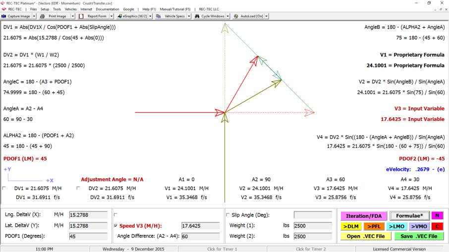
Figure 612-IM53
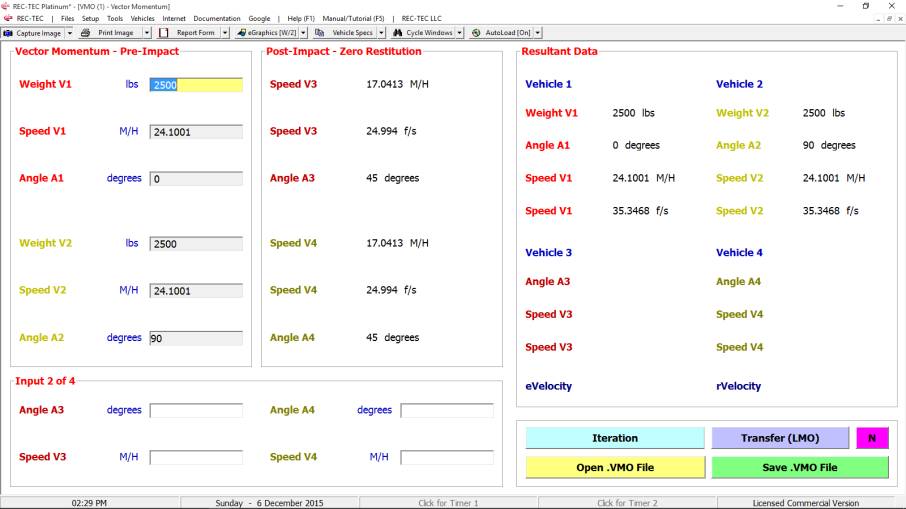
Well, not exactly, but we do have more options. This module allows us to use either angles,
speeds or a combination of an angle and a speed, and the combination can be on
the same vehicle or different vehicles.
More options just might let us solve the problem. Use 60 degrees for Angle A3 and 17.6425 for
the speed of V4.
Figure 612-IM54
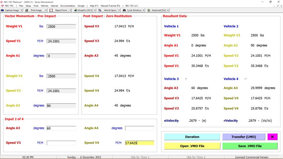
It has calculated A4 to be 29.9999 - remember, the program
truncates at the requested decimal place (1-4). This gives us a lot of flexibility because it gives us more
options. Crush5 (Crash3) gives but one
option, it needs the departure angles.
Vector Momentum permits six (6) different options. More options give more possibilities for
solving the problem, the ultimate goal.
Figure 612-IM55
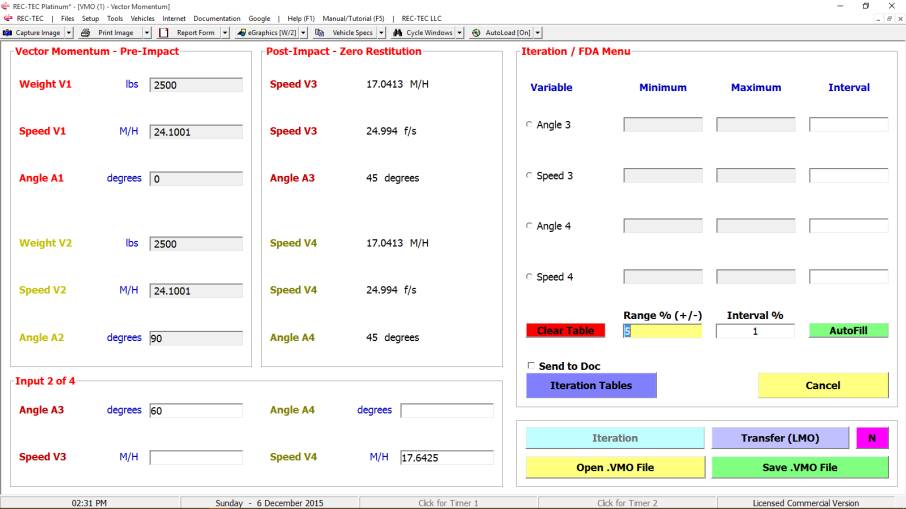
Enter Range and Interval parameters and then use Autofill
to populate the interface.
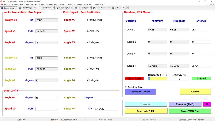
Figure 612-IM56
The module only sets the parameters for Minimum, Maximum,
and Interval for the Inputs entered into the Main Interface. While the values can be changed by the user
even for the unavailable variables, they may not be selected for Iteration.
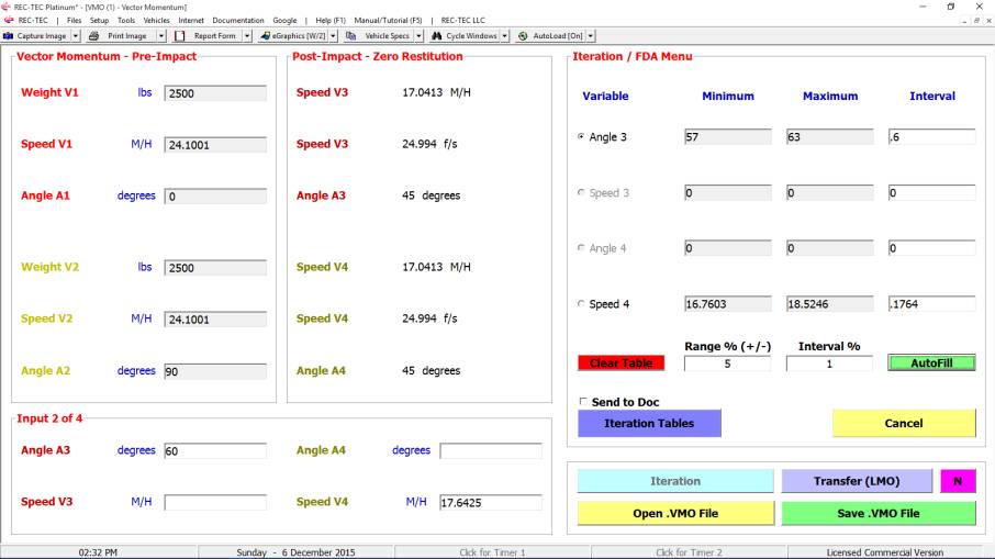
Figure 612-IM57
The radio buttons on the left side of the table allow
Selecting a particular Variable (Angle 3 in this instance) as the default
value. This value will be transferred
to the Main Interface and the Iteration Interface will be reset (AutoFill)
automatically. The 63 degree angle will
be selected to demonstrate this capability.
Figure 612-IM58
The transfer was automatic and the program recalculated the
output based on the new value for Angle 3.
Figure 612-IM59
This new Iteration data will be used to generate a new
table for Speed 4.
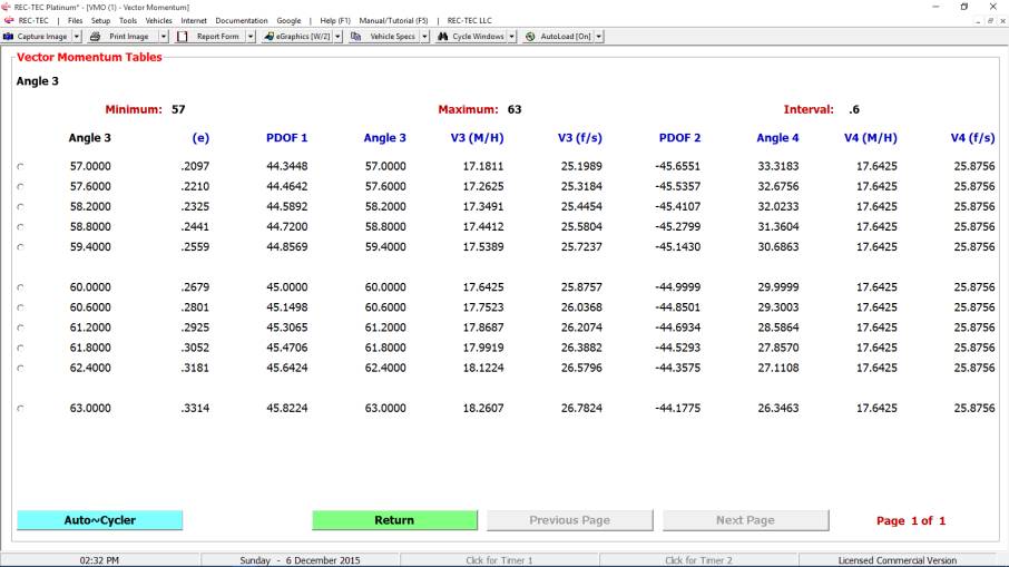
Figure 612-IM60
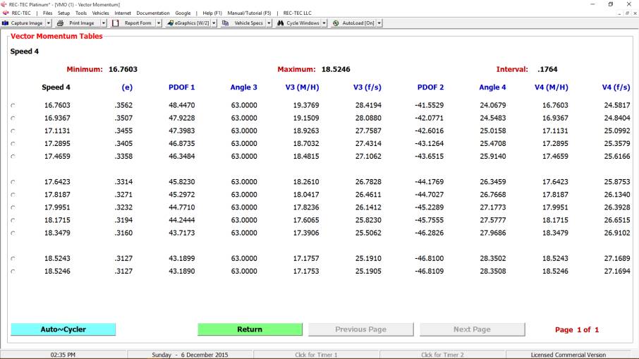
Shown above the data
for Speed 4 Iteration. Note that the
Restitution and PDOF values for all of these changes are an integral part of
the tables. This gives a fuller picture
of how changing post-impact angles and departure speeds affects the collision.
Figure 612-IM61
If reliable data from other sources is available for the
pre-impact or the post-impact speeds of one of the vehicles, approach and
departure angles for that vehicle can be calculated if the angular difference
between the pre and post-impact vehicle is known. Assume we have a V1 of 24.1001 M/H and a V3 of 17.6425 M/H with a
angular difference of 60 degrees between pre and post-impact. Check Angle2 checkbox.
Figure
612-IM62
In this
step we have set the Impact Speed of Vehicle 1.
Figure
612-IM63
Here we
have set the Post-Impact Speed of Vehicle 1 (V3).
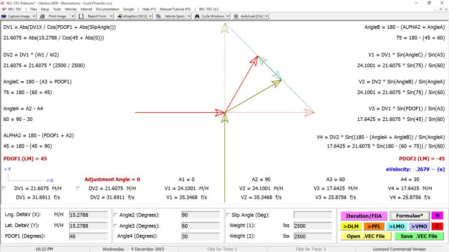
Figure
612-IM64
Note: Using correct values for the problem as entered input
values kept the proper relationship for the PDOF, DVx, and DVy values. Use of "override" values will
cause an imbalance that may be unacceptable.
Conclusion:
This paper presents a viable alternative to the CDR only
solution when reconstructing
accidents. REC-TEC
integrating Crush5, 360 Linear Momentum, Vectors (EDR -
Momentum), and Vector Momentum Analysis can combine to produce an
absolutely stunning array of unique attributes specifically designed to assist
in forming your opinions, and reinforcing your informed opinions. If CDR data
on pre-impact and/or post-impact speeds is available, Vectors (EDR -
Momentum), Vector Momentum Analysis, and Triangle Solver can
be used in arriving at a solution.
While the expert is always limited by the data available in
forming opinions, sometimes more data is available than first believed, and
using all of the data in new and different ways can present a new way of
approaching the problem. It has been
the objective herein to provide some outside of the usual box approaches to
collisions where data was at best limited.
SMAC (2D and 3D) from
several companies, "Crash" variants, and several Point-Click-Drag
high-resolution animation packages are available, several costing $10,000
or more for a package that is very limited in scope (and installations). Some
require minimal training of only a few hours with no emphasis on the physics
behind the curtain. All are still
limited to the data available to the reconstructionist, although this
requirement is all too often waived in an effort to let the computer supply the
Suspension of Disbelief for the viewer.
Besides some very fancy (and blatantly overly prejudicial) bells and
whistles that will certainly impress an uneducated trier of fact, exactly what
do these animations (based on simulations that are often based on opinions, or
based purely on opinion) really offer?
They have been lumped together because most of the time they all
accomplish the same thing - a glitzy view of an opinion of one possible
solution that could have happened by a (highly-skilled) expert.
Lest someone think this is an overly harsh critique of SMAC,
Crash variants, and Point-Click-Drag high-resolution animation, REC-TEC
also includes a very efficient SMAC module that is integrated with Crush5
and 360 LM providing a startlingly easy way to set inputs for SMAC
simulation>animation. As recommended by many experts, SMAC et al and CDR
data are excellent secondary, or tertiary tools, when used to verify the
reconstruction. They were never meant to be the primary tool for
"doing" the reconstruction..
In a perfect world, a satellite capable of high-resolution
and high-speed image capture would provide a video of our collision, which
rarely, if ever, happens. REC-TEC
is the next best option.
Question Everything!
Copyright George M. Bonnett, JD 2015 All Rights
Reserved